Audio Recording
- Introduction
- Background
- Code Layout
- Configuration
- Firmware Implementation
- MATLAB Host
- Stability
- Showcase
- Developer Notes
Introduction
The Audio Recording project turns SensEdu into a continuous PCM audio recorder. Microphone data is sampled at 44.1 kHz, buffered locally on the board, and streamed over USB to a MATLAB host that saves it as a WAV file and plots its time-domain waveform and spectrum.
The project is built around a problem: the USB transfer that is supposed to deliver the recording also injects noise into the analog input. The architecture is designed to limit USB transfers to brief bursts, so the noise appears only at the segment boundaries instead of being spread across the whole recording. This project covers DMA double-buffering, external SDRAM, framed serial protocols, and recoverable error handling – all common building blocks of more advanced acquisition systems.
Background
PCM Audio
Pulse Code Modulation (PCM) represents an analog audio signal digitally using two main parameters:
- Sampling rate (\(F_s\)): how often the ADC samples the input. CD audio uses \(F_s = 44.1\text{ kHz}\), which covers the full audible range.
- Bit depth: the resolution of each sample. The STM32H7 ADC in this project produces 16-bit values.
A 30-second recording at these settings is therefore \(44100 \times 30 \times 2 = 2.646\text{ MB}\). This is too large for on-chip SRAM but well within the GIGA’s 8 MB of external SDRAM.
USB-Injected Noise
Whenever a high-speed digital interface like USB Full-Speed (12 Mbps) shares a PCB with a sensitive analog circuit, layout becomes the dominant factor in noise performance. The audible artifact is usually a high-pitched whine or buzz that tracks USB activity. This is fundamentally a property of the Arduino GIGA R1 itself, not something the SensEdu shield can fix.
Two coupling mechanisms are typically at play:
- Ground-return coupling: return currents from the USB lines flow through the ground plane shared with the ADC, producing a small voltage drop across the finite resistance and inductance of the plane. The analog input, which references the same ground, sees that drop as common-mode noise.
- Capacitive coupling: parasitic capacitance between adjacent USB and analog traces lets some USB signal couple directly into the analog trace, where it appears as a voltage glitch.
A look at the official GIGA R1 schematics confirms that analog and digital grounds are not separated, which is what an audio-focused board would do differently. A full investigation of the problem would require an analysis of PCB files here.
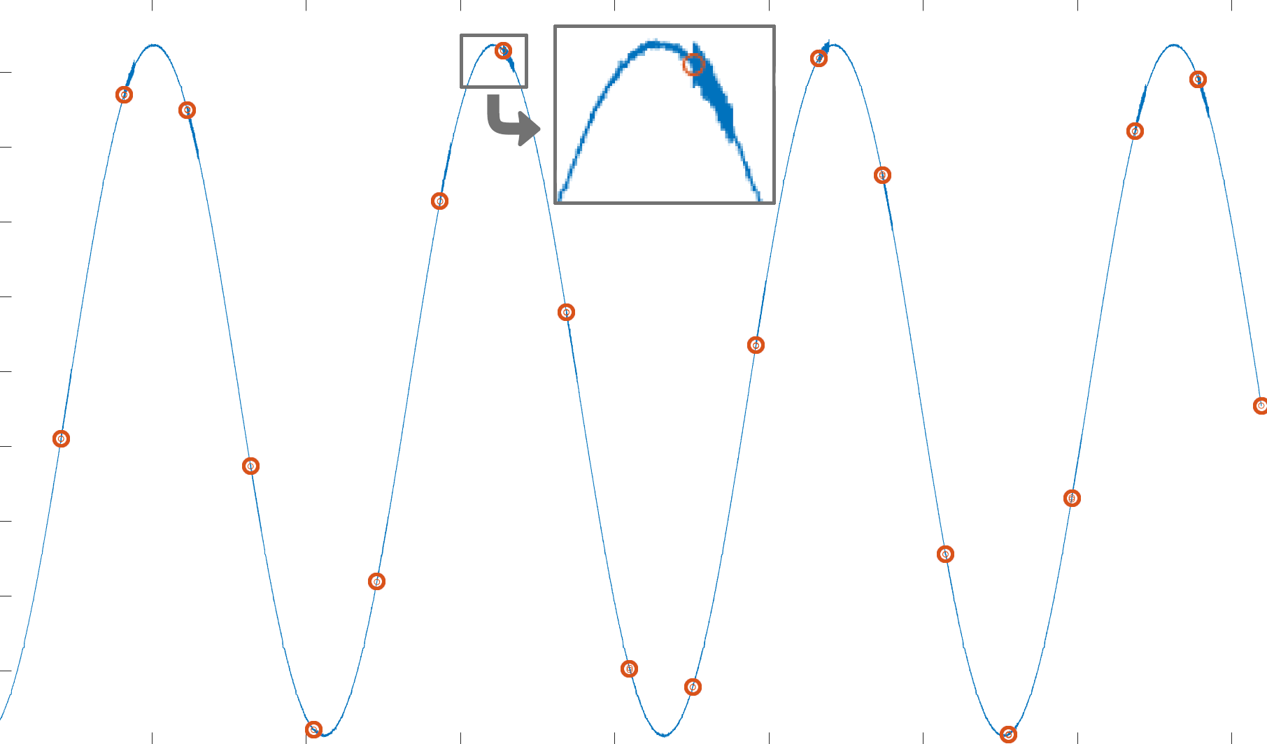
Since we can’t change the hardware, the firmware works around it. The classical “stream every sample as it arrives” architecture spreads this noise uniformly through the recording. An example of such a recording:
For better visualization, I connected a sinusoid from a signal generator to the input. The signal is sampled with parallel USB requests at the beginning of each DMA half-buffer. Orange circles on the plot separate these “segments”. USB transfers are visible as high-frequency bursts of noise at the beginning of each half-buffer.
This issue is the reason why a batched transfers architecture is used instead. The firmware records audio into SDRAM with no concurrent USB activity, then dumps a whole SDRAM segment over USB at once. The audible result is that the noise is confined to short bursts between much larger segments, leaving the rest of the audio clean. See SDRAM Slot Ring and Transfer Pipeline for how this is implemented.
Code Layout
The firmware is a single .ino file and the host is a single .m file. Everything lives under projects/Audio_Recording/.
| File | Purpose |
|---|---|
Audio_Recording.ino
| Entry point. ADC + DMA + SDRAM setup, command parser, capture pipeline, USB transfer pipeline. |
matlab/Audio_Recording.m
| Host script. Opens the serial port, drives the start/stop handshake, reads framed segments, saves the WAV file, plots waveform + FFT. |
Configuration
All tunable constants live at the top of Audio_Recording.ino:
| Constant | Default | Meaning |
|---|---|---|
SAMPLING_RATE
| 44100 | ADC sampling rate in Hz. |
CHUNK_SIZE
| 256 | DMA half-buffer size in samples. |
SEGMENT_SECONDS
| 30 | Length of each SDRAM slot. Each slot consumes SAMPLING_RATE × SEGMENT_SECONDS × 2 bytes.
|
SEGMENT_NUM
| 2 | Number of SDRAM slots in the ping-pong. Total SDRAM footprint = SEGMENT_NUM × per-slot bytes; must stay under 8 MB.
|
USB_CHUNK_BYTES
| 4080 | Payload bytes per Serial.write call. Deliberately not a multiple of 64; see USB Short Packet.
|
On the MATLAB side:
| Variable | Default | Meaning |
|---|---|---|
ARDUINO_PORT
| 'COM16'
| GIGA serial port. |
RECORDING_DURATION_SEC
| 40 | Desired recording length. The host requests ceil(duration / SEGMENT_SECONDS) segments and trims the excess.
|
ENABLE_PLAYBACK
| true
| Auto-play the recording when the script finishes. |
Firmware Implementation
This section describes the general idea behind the firmware implementation. Refer to the full source under projects/Audio_Recording/ for the complete picture.
State Machine
The firmware lives in one of two states:
STATE_IDLE– ADC is OFF, no slots are filling, no data is being transmitted. Default after boot.STATE_RECORDING– ADC is ON, DMA is filling the SRAM ping-pong, and the main loop is copying samples to SDRAM and (when a slot fills) transmitting them.
Transitions are driven by host commands, covered in Session Lifecycle. The main loop itself is non-blocking and stateless beyond these two states:
void loop() {
    process_command();
    process_capture();
    process_usb_transfer();
}
Each function does at most one unit of work per iteration. The loop never blocks on long operations.
SDRAM Slot Ring
The Arduino GIGA’s on-chip SRAM is too small for the multi-megabyte recordings we are targeting, so the slots live in the GIGA’s external 8 MB SDRAM. Each slot has its own buffer plus metadata.
typedef struct {
    uint16_t* buffer;        // SDRAM buffer pointer (allocated once at boot, never freed)
    uint32_t  sequence_id;   // 0-based id within the current firmware session
    uint32_t  sample_count;  // Valid sample count in this slot
    uint32_t  flags;
    bool      ready;
} Slot;

static Slot slots[SEGMENT_NUM];
Buffers are allocated once at boot via the bundled SDRAM library and never freed for the rest of the program’s life. This is the only dynamic allocation in the whole firmware:
static bool allocate_sdram() {
    for (uint8_t i = 0; i < SEGMENT_NUM; i++) {
        slots[i].buffer = (uint16_t*)SDRAM.malloc(SEGMENT_BYTES);
        if (slots[i].buffer == NULL) {
            return false;
        }
    }
    return true;
}
The slots[] array is then treated as a ring, with two state structs tracking the producer (capture) and consumer (transfer) sides independently:
typedef struct {
    uint8_t  write_idx;         // Currently filling slot
    uint32_t captured_samples;  // Samples written into the current slot so far
    uint32_t next_sequence_id;  // Next id to assign on slot completion
} CaptureState;

typedef struct {
    int8_t   slot_idx;     // Slot being transmitted (NO_SLOT if none)
    uint32_t bytes_sent;   // Payload bytes already sent for the current slot
    bool     header_sent;  // Header already sent for the current slot
    bool     tail_sent;    // Tail magic already sent for the current slot
} TransferState;
- Capture side (
CaptureState) writes intoslots[capture.write_idx]. When the slot fills it setsready = trueand advances to the next index. - Transfer side (
TransferState) picks whichever slot hasready == trueand the lowestsequence_id, transmits it, then setsready = false.
The ready flag is the only synchronization between the two sides.
Capture Pipeline
process_capture polls the two DMA flags. Whenever either fires, it copies the corresponding half of the SRAM ping-pong into the current SDRAM slot:
static void process_capture() {
    if (fw_state != STATE_RECORDING) return;

    if (SensEdu_ADC_IsDmaHalfTransferComplete(adc)) {
        SensEdu_ADC_ClearDmaHalfTransferComplete(adc);
        save_dma_half(&dma_buf[0], DMA_BUF_SIZE / 2);
    }
    if (SensEdu_ADC_IsDmaTransferComplete(adc)) {
        SensEdu_ADC_ClearDmaTransferComplete(adc);
        save_dma_half(&dma_buf[DMA_BUF_SIZE / 2], DMA_BUF_SIZE / 2);
    }
}
save_dma_half is where the slot ring actually advances. A 256-sample DMA half-buffer almost never divides the slot size evenly, so the same call that finishes one slot also has to begin filling the next one:
static void save_dma_half(volatile uint16_t* src, uint16_t src_length) {
    uint16_t copied = 0;
    while (copied < src_length) {
        if (slots[capture.write_idx].ready) {
            pending_overrun_flag |= FLAG_OVERRUN_DROPPED;
            return;
        }

        uint16_t* dst = slots[capture.write_idx].buffer;
        uint32_t remaining_in_slot = SEGMENT_SAMPLES - capture.captured_samples;
        uint32_t to_copy = (uint32_t)(src_length - copied);
        if (to_copy > remaining_in_slot) {
            to_copy = remaining_in_slot;
        }

        for (uint32_t i = 0; i < to_copy; i++) {
            dst[capture.captured_samples + i] = src[copied + i];
        }
        capture.captured_samples += to_copy;
        copied += (uint16_t)to_copy;

        if (capture.captured_samples >= SEGMENT_SAMPLES) {
            mark_slot_ready();
        }
    }
}
mark_slot_ready hands the just-filled slot off from the capture side to the transfer side. Once ready flips to true, the next call to process_usb_transfer is free to pick it up.
static void mark_slot_ready() {
    uint8_t idx = capture.write_idx;
    slots[idx].sequence_id  = capture.next_sequence_id++;
    slots[idx].sample_count = SEGMENT_SAMPLES;
    slots[idx].flags        = pending_overrun_flag;
    slots[idx].ready        = true;
    pending_overrun_flag    = 0;

    capture.captured_samples = 0;
    capture.write_idx = (uint8_t)((idx + 1) % SEGMENT_NUM);
}
Slot Overrun
If the host stalls for long enough that the next SDRAM slot isn’t yet free when capture needs it, the firmware drops the incoming DMA samples and sets FLAG_OVERRUN_DROPPED so that the next emitted header carries a “samples were lost before this segment” notice. The host warns the user and keeps going. Dropping rather than halting keeps the firmware recoverable.
if (slots[capture.write_idx].ready) {
    pending_overrun_flag |= FLAG_OVERRUN_DROPPED;
    return;
}
Transfer Pipeline
Once a slot is ready, process_usb_transfer sends a 20-byte header, then the raw sample bytes in USB_CHUNK_BYTES pieces, and finally an 8-byte trailer. The trailer acts as a framing integrity check; see Why a Segment Tail for the details.
The slot to transmit is chosen by lowest sequence_id, not by lowest index, because the host validates strict sequence ordering on every header:
int8_t best = NO_SLOT;
uint32_t best_seq = 0;
for (uint8_t i = 0; i < SEGMENT_NUM; i++) {
    if (!slots[i].ready) continue;
    if (best == NO_SLOT || slots[i].sequence_id < best_seq) {
        best = (int8_t)i;
        best_seq = slots[i].sequence_id;
    }
}
Header and trailer each have their own struct and magic word (a fixed constant both sides agree on to confirm frame alignment), so the host can verify framing and integrity immediately on arrival:
typedef struct {
    uint32_t magic;
    uint32_t session_id;
    uint32_t sequence_id;
    uint32_t sample_count;
    uint32_t flags;
} SegmentHeader;

typedef struct {
    uint32_t magic;
    uint32_t sequence_id;
} SegmentTail;
Session Lifecycle
For clean restarts from the host, every new session needs a clean firmware state. reset_pipeline zeroes every ring index, slot flag, and transfer cursor. It does not touch the SDRAM buffer pointers or the session_id:
static void reset_pipeline() {
    for (uint8_t i = 0; i < SEGMENT_NUM; i++) {
        slots[i].ready = false;
        slots[i].sequence_id = 0;
        slots[i].sample_count = 0;
        slots[i].flags = 0;
    }
    capture.write_idx = 0;
    capture.captured_samples = 0;
    capture.next_sequence_id = 0;
    transfer.slot_idx = NO_SLOT;
    transfer.bytes_sent = 0;
    transfer.header_sent = false;
    transfer.tail_sent = false;
    pending_overrun_flag = 0;
}
Host commands drive the state transitions. The 's' command invokes cmd_start, which brings the firmware into a clean recording state regardless of what it was doing before:
static void cmd_start() {
    SensEdu_ADC_Disable(adc);
    SensEdu_ADC_ClearDmaTransferComplete(adc);
    SensEdu_ADC_ClearDmaHalfTransferComplete(adc);

    reset_pipeline();
    session_id++;
    fw_state = STATE_RECORDING;

    send_ack('s', 0);

    SensEdu_ADC_Enable(adc);
    SensEdu_ADC_Start(adc);
}
session_id is incremented on every start. The host captures the new value from the start ACK and validates it on every subsequent frame, so any leftover data from a prior session is rejected automatically.
The ACK is emitted before the ADC is re-enabled. If the ADC were running while the ACK was being written, a slow Serial.write could let the first DMA half-buffer fill and be overwritten, even before the main loop got a chance to drain it.
The 'p' command invokes cmd_stop, which brings the firmware back to idle. It also reports the number of completed segments in the ACK’s info field for the host’s own logging:
static void cmd_stop() {
    if (fw_state == STATE_RECORDING) {
        SensEdu_ADC_Disable(adc);
        fw_state = STATE_IDLE;
    }

    uint32_t segments_completed = capture.next_sequence_id;
    reset_pipeline();
    send_ack('p', segments_completed);
}
The '?' command is a status query. The ACK carries the current state and the number of samples already captured into the active slot:
static void cmd_status() {
    send_ack('?', capture.captured_samples);
}
MATLAB Host
The host script is located at projects/Audio_Recording/matlab/Audio_Recording.m. It opens the serial port, drives the start/stop handshake, reads framed segments into a buffer, saves the result as a WAV file, and plots the waveform and magnitude spectrum.
Restart-Safe Handshake
After opening the serial port, the script sends 'p' to bring the firmware to a known idle state. This works regardless of what the firmware was doing: finishing a transfer from a previous run, mid-recording, or idle. Then 's' starts a fresh session and the start ACK carries the new session_id:
write(arduino, uint8('p'), 'uint8');
read_ack(arduino, 'p', FIRST_ACK_WAIT_SEC, RESYNC_MAX_BYTES, ACK_MAGIC, ACK_BYTES);

write(arduino, uint8('s'), 'uint8');
start_ack  = read_ack(arduino, 's', ACK_WAIT_SEC, ACK_BYTES * 2, ACK_MAGIC, ACK_BYTES);
session_id = start_ack.session_id;
Framed Reading
Every frame from the firmware is read through a single helper, read_framed, that locates the magic word and applies a per-frame validator:
- Read
frame_bytesfrom the port. - If the first 4 bytes match the magic and the validator accepts the frame, return it.
- Otherwise, slide forward looking for the magic; repeat. Abort once
max_resync_byteshave been scanned.
The validator performs the structural sanity check:
- For segment headers: requires
session_idto match the active session andsample_countto be within bounds - For ACKs: requires
cmdto be the one we just sent
function ok = seg_is_valid(buf, expected_session_id, max_samples)
    session_id   = typecast(uint8(buf(5:8)),   'uint32');
    sample_count = typecast(uint8(buf(13:16)), 'uint32');
    flags        = typecast(uint8(buf(17:20)), 'uint32');
    ok = (session_id == expected_session_id) && (sample_count > 0) ...
         && (sample_count <= max_samples) && (flags <= 1);
end

function ok = ack_is_valid(buf, expected_cmd)
    cmd_char = char(buf(5));
    state = buf(6);
    pad = typecast(uint8(buf(7:8)), 'uint16');
    ok = (cmd_char == expected_cmd) && (state == 0 || state == 1) && (pad == 0);
end
The read_framed implementation reads the stream in 64 KB chunks (defined by SCAN_CHUNK) and locates the magic with a find_pattern byte-search helper.
Segment Receive Loop
With the session live, the host requests SEGMENTS_TO_RECORD audio segments. Each iteration reads the three pieces in order: header, payload, and tail; verifies the header and tail, and saves the payload by copying it into the data_full buffer:
for seg = 1:SEGMENTS_TO_RECORD
    hdr = read_segment_header(arduino, HEADER_WAIT_SEC, RESYNC_MAX_BYTES, ...
                              SEG_MAGIC, SEG_HDR_BYTES, session_id, SEGMENT_SAMPLES);

    if double(hdr.sequence_id) ~= (last_seq_id + 1)
        partial_recording = true;  break;     % sequence gap, keep what we have
    end
    last_seq_id = double(hdr.sequence_id);

    samples = read_samples(arduino, double(hdr.sample_count), PAYLOAD_WAIT_SEC);
    tail_ok = read_segment_tail(arduino, PAYLOAD_WAIT_SEC, SEG_TAIL_MAGIC, ...
                                SEG_TAIL_BYTES, hdr.sequence_id);

    data_full(write_pos + 1 : write_pos + numel(samples)) = samples;
    write_pos = write_pos + numel(samples);

    if ~tail_ok
        partial_recording = true;  break;     % stream drift, keep what we have
    end
end
When the sequence_id jumps or the tail magic doesn’t match, the loop breaks and the script saves whatever it captured so far. See Why a Segment Tail for why the tail check matters.
Saving and Plotting
After the loop, the host sends 'p' to stop the session and trims data_full to either write_pos (what was actually captured) or RECORDING_DURATION_SEC * Fs (the requested length), whichever is smaller. If any segments carried FLAG_OVERRUN_DROPPED or the recording ended early, a warning is printed before saving.
The 16-bit unsigned ADC samples are then normalized to the [-1, +1] range that audiowrite expects, and the residual DC bias from the microphone preamp is subtracted:
y = data_full / 65535;
y = 2 * y - 1;
y = y - mean(y);
audiowrite(file_name, y, Fs);
The file is written to Recordings/recorded_audio_<timestamp>.wav, and the script finally plots the time-domain waveform and the magnitude spectrum (and optionally plays the result if ENABLE_PLAYBACK is set).
Stability
Before the showcase, we should address the elephant in the room – the sheer number of handshakes, checks, and guards in the firmware and host.
The USB data transfer between the Arduino GIGA R1 and MATLAB is not something we designed, and it is not really suited for this application. It uses general-purpose USB CDC, which by design is allowed to drop bytes when the host is busy or stalls, thus very awkward to deal with for a real-time application like audio recording. In other projects we never minded the occasional dropped bytes since only the last small chunk of data really mattered. But here, the audio is a long, continuous stream that is expected to be perfectly uninterrupted.
This is easy to see for yourself – try running the host script with MATLAB being the only running software and as the current active window. Just sit and wait; it should complete reliably almost every single time, without any warnings.
Afterwards, try starting the script while browsing the web, watching a video, or copying some files. You’ll see the script throw warnings far more often.
All the handshakes exist to ensure that dropped bytes are detected and handled cleanly, so the data that was successfully acquired is still saved, and the application can be restarted smoothly.
Showcase
Segment length is set to 30 seconds for these recordings. You should hear a brief USB-injected noise at each segment boundary.
Ambient
Recorded on the balcony on a summer day.
Music
Hod Battle from Library of Ruina playing about 40 cm from the board at a 90° angle, through a Bluetooth speaker.
Voice
Voice lines of Andre the Blacksmith from Dark Souls III playing about 40 cm from the board at a 90° angle, through a Bluetooth speaker.
Developer Notes
USB Short Packet
The Windows USB CDC (Communications Device Class) driver delivers bulk data only when one of three things happens:
- Driver’s read buffer fills (typically 4096 B)
- Short packet (< 64 B) arrives
- Read timeout expires
If every Serial.write is an exact multiple of 64 B, no short packet is ever produced and trailing bytes sit in the driver’s buffer until the read times out.
Firmware must use sizes that are not a multiple of 64 B to end with a short packet
static const uint32_t USB_CHUNK_BYTES = 4080; // 63 * 64 + 48
The trailing 48-byte chunk is the short packet that flushes the buffer.
Serial.flush() does not help.
Why a Segment Tail
The segment header alone is enough to frame the payload (the host knows how many bytes to read from sample_count), but it cannot verify that the firmware and host agree on the byte count.
If the firmware ever sends fewer or more bytes than the header announced, the host’s blocking read would silently consume the wrong bytes and the misalignment would only surface later as a corrupted next header or a sequence-id discontinuity. The trailer turns this silent drift into an immediate, localized failure.
On mismatch the host emits a warning, stops the loop, trims data_full to whatever was successfully captured, and saves the partial WAV.