PCB Design
SensEdu focuses on the design and development of a Printed Circuit Board (PCB) tailored for the Arduino GIGA R1. The objective is to create a versatile and efficient platform capable of accommodating a wide range of ultrasound applications, ensuring optimal performance and ease of integration.
- Overview
- Schematics
- Software
- PCB Layout
- Power Supply
- MEMS Microphones (Infineon IM73A135V01XTSA1)
- Amplifier
- I2C based Sensors
- Ultrasound Transmission
Overview
This shield extends the Arduino GIGA’s capabilities for ultrasound applications, including:
- 4-channel MEMS microphone array (Infineon IM73A135V01) for signal acquisition
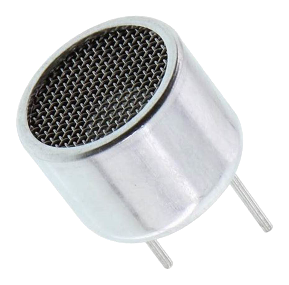
- Ultrasonic transmitters (Prowave 328ST160) for generating 32.8 kHz signals
- Multi-voltage LDOs for stable digital power and symmetric transmitter driving
- DPS368 barometric sensor for environmental compensation
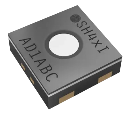
- SHT40-AD1F temperature and humidity sensor for environmental compensation
Schematics
Software


The PCB for this project was designed using KiCad in Version 9.0, an open-source software suite for electronic design automation (EDA). KiCad offers a comprehensive set of tools for schematic capture, PCB layout, and 3D visualization.
The symbols and footprints are integrated into the project with internal project libraries. If you encounter an error, make sure that these are correctly referenced.
PCB Layout
4-Layer Stackup:
- Top Layer: Signal routing for components with ground plane fill
- Layer 2: Solid ground plane
- Layer 3: Power planes (3.3 V, 2.5 V, 1.25 V)
- Bottom Layer: Signal routing for components with ground plane fill
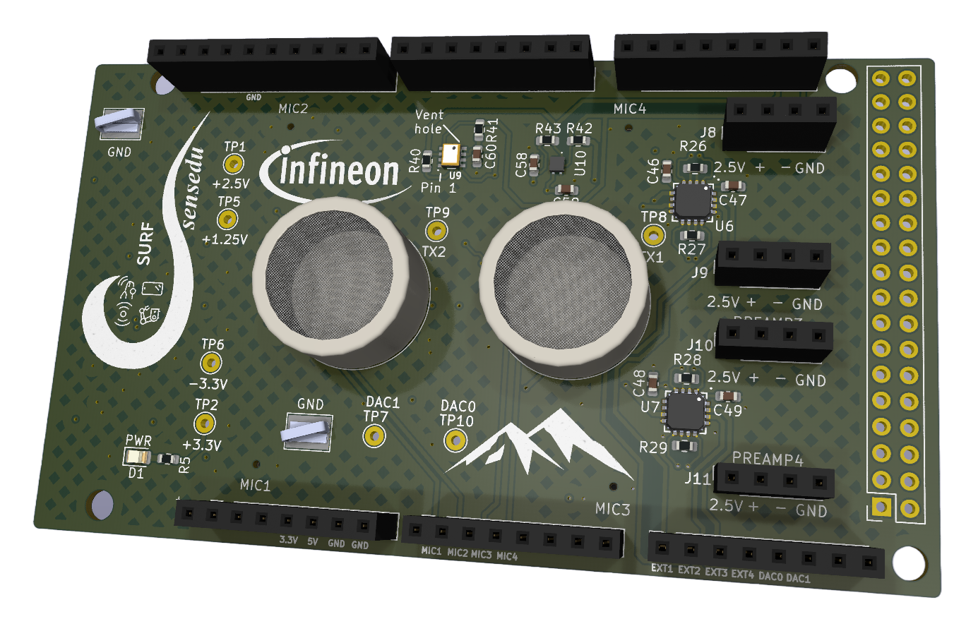
Front side
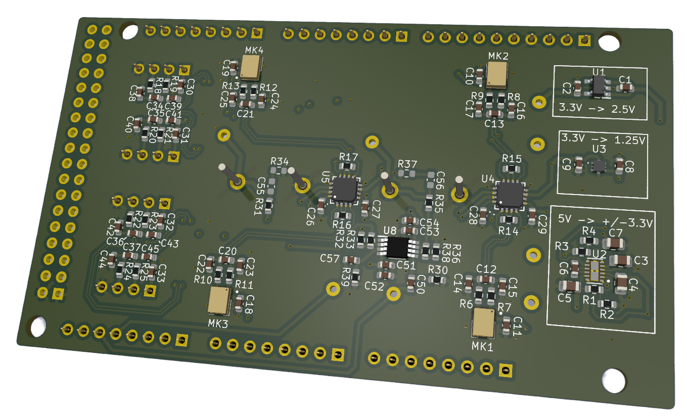
Back side
Power Supply
Key Components:
- Primary supply IC (Texas Instruments LM27762DSST):
- Converts 5 V (Arduino) to +3.3 V and -3.3 V for the shield
- Secondary LDOs:
- LDLN025M25R: Provides 2.5 V for microphone supply
- TS3312AQPR: Provides 1.25 V reference for amplifier offset
Power Paths:
5 V]) --> B[LM27762
Charge Pump+LDO] B --> P[[+3.3 V rail]] B --> N[[-3.3 V rail]] P --> V25[[+2.5 V rail]] P --> V125[[+1.25 V rail]] %% Node styling classDef src fill:#f1f5f9,stroke:#334155,stroke-width:1.5px,rx:6,ry:6; classDef ic fill:#fff7ed,stroke:#9a3412,stroke-width:1.5px,rx:6,ry:6; classDef pos fill:#eff6ff,stroke:#1d4ed8,stroke-width:1.5px,rx:6,ry:6; classDef neg fill:#fef2f2,stroke:#b91c1c,stroke-width:1.5px,rx:6,ry:6; class A src; class B ic; class P,V25,V125 pos; class N neg; %% Link styling (order = appearance) linkStyle 0 stroke:#334155,stroke-width:2px; linkStyle 1 stroke:#1d4ed8,stroke-width:2px; linkStyle 2 stroke:#b91c1c,stroke-width:2px; linkStyle 3 stroke:#1d4ed8,stroke-width:2px,stroke-dasharray:5 4; linkStyle 4 stroke:#1d4ed8,stroke-width:2px,stroke-dasharray:5 4;
Indicators:
- Green LED lights up when 3.3 V is active
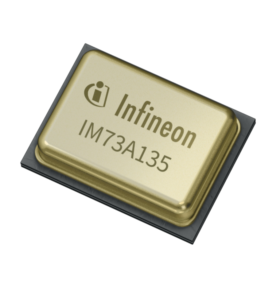
MEMS Microphones (Infineon IM73A135V01XTSA1)
The Infineon IM73A135V01XTSA1 is a high-performance analog MEMS microphone designed for precise sound capture. It is suitable for ultrasound applications due to its high Signal-to-Noise Ratio (SNR) and low Total Harmonic Distortion (THD).
- Quantity: 4
- Key Features:
- SNR: 73 dB, which is excellent for capturing low-level ultrasonic signals with high fidelity
- Frequency Response: Wide and flat frequency response suitable for ultrasonic frequencies
- Sensitivity: -38 dBV/Pa, enabling detection of weak ultrasonic signals
- Low Power Consumption: Efficient power usage, critical for battery-operated or low-power applications
- Power Supply:
- 2.5 V supply from the LDLN025M25R LDO
Amplifier
- Instrumentation Amplifier (AD8426ACPZ):
The AD8426ACPZ is a high-performance instrumentation amplifier from Analog Devices. It is designed for accurate, low-noise amplification of small differential signals, making it ideal for amplifying the weak signals from the MEMS microphones in ultrasound applications.
- Key Features:
- Low Noise: 1 nV/√Hz noise density, ensuring minimal introduction of noise into the signal
- High Common-Mode Rejection Ratio (CMRR): Ensures that noise from the power supply or other sources is minimized
- Single-Supply Operation: 3.3 V supply voltage, compatible with the overall system design
- Configurable Gain: Gain can be set using external resistors, with a typical configuration providing a gain of 50 (using a 1 kΩ resistor)
- Usage in Design:
- Microphone Signal Amplification: The AD8426 amplifiers are used to boost the small amplitude signals from the MEMS microphones (IM73A135V01XTSA1) to levels that fully utilise the range of the internal ADCs
- Configuration: 4x AD8426 amplifiers provide four channels of amplification, each with a gain of 50. Two of them are for the Infineon IM73A135V01XTSA1 microphones and two for external sources
- Amplifier for external signals: J8/J9/J10/J11: 4-pin headers for connecting external microphones or other signal sources
- Pin 1: 2.5 V (mic supply)
- Pin 2: Amplifier input +
- Pin 3: Amplifier input -
- Pin 4: GND
- Power Supply: Operates with single 3.3 V supply
Analog Input Connections
| Input | Amplifier Channel | Arduino Pin | STM32 Pin | Available ADCs |
|---|---|---|---|---|
| MK1 | U4 CH1 | A0 | PC4_C | ADC1 & ADC2 |
| MK2 | U4 CH2 | A1 | PC5_C | ADC1 & ADC2 |
| MK3 | U5 CH1 | A2 | PB0_C | ADC1 & ADC2 |
| MK4 | U5 CH2 | A3 | PB1_C | ADC1 & ADC2 |
| J8 | U6 CH1 | A8 | PC2_C | ADC3 |
| J9 | U6 CH2 | A9 | PC3_C | ADC3 |
| J10 | U7 CH1 | A10 | PA1_C | ADC1 & ADC2 |
| J11 | U7 CH2 | A11 | PA0_C | ADC1 & ADC2 |
I2C based Sensors
Two different sensors are used to gain additional information about the environment to increase the accuracy of the measurements. The communication with these is implemented by I2C bus. I2C2 (D20 and D21) corresponds to the correct instance of the Arduino.
| Sensor | Address |
|---|---|
| DPS368 | 0x77 |
| SHT40-AD1F | 0x44 |
Use Wire (D20/D21) to be able to talk to the sensors via I2C (Default) of the Arduino GIGA.
Barometric Pressure Sensor (Infineon DPS368)
The DPS368 is a high-precision barometric pressure sensor designed by Infineon. It measures both pressure and temperature, providing essential environmental data that can be used to compensate for variations in ultrasound propagation due to changes in atmospheric conditions.

- Interface: I2C
- Key Features:
- Pressure Range: 300 to 1200 hPa, suitable for most environmental conditions
- Temperature Range: -40 to 85 °C, allowing for robust operation in various environments
- High Accuracy: Pressure accuracy of ±1 hPa and temperature accuracy of ±0.5 °C, ensuring precise environmental compensation
- Low Power Consumption: Ideal for continuous monitoring without significant power drain
- Power Supply: Operates with single 3.3 V supply
- Usage:
- The DPS368 is used to measure atmospheric pressure and temperature, which are used for weather information and forecasts as well as for adjusting the ultrasound measurements for more accurate distance and velocity calculations by adressing a potential change in altitude and corresponding change of sound wave velocity.
Humidity and Temperature Sensor (Sensirion SHT40-AD1F)
The SHT40-AD1F is a high-precision humidity and temperature sensor designed by Sensirion. It measures both humidity and temperature, providing essential environmental data with a short start-up time.
- Interface: I2C
- Key Features:
- Humidity Range: 0 to 100 % relative humidity (RH)
- Temperature Range: -40 to 125 °C, allowing for robust operation in various environments
- High Accuracy: Humidity accuracy of ±1.8 % RH and temperature accuracy of ±0.2 °C
- Low Power Consumption: Ideal for continuous monitoring without significant power drain
- Power Supply: Operates with single 3.3 V supply
- Usage:
- The SHT40-AD1F is used to measure relative humidity and temperature, which are used used for weather information and forecasts
Ultrasound Transmission
Ultrasound Speakers (Prowave 328ST160)
The Prowave 328ST160 is an ultrasound speaker designed specifically for emitting high-frequency sound waves. With a resonance frequency of 32.8 kHz, it is ideal for generating ultrasound signals that can be used in various applications such as distance measurement and object detection.
- Key Features:
- Resonance Frequency: 32.8 kHz, which is optimal for many ultrasound applications
- High Sound Pressure Level (SPL): Ensures strong and consistent ultrasound signal transmission
- Directional Beam Pattern: Focuses the ultrasound waves, improving accuracy in detecting object reflections
- Durability: Designed to withstand environmental factors, making it suitable for both indoor and outdoor applications
- Integration in Design:
- Driving Circuit: The ultrasonic speakers are driven by the ADA4511-2 operational amplifier, which provides the necessary gain and power to achieve optimal performance
- 2x Speakers (LS1&LS2)
- Signal Input Options:
- Analog Waveforms: Provided through Arduino DAC pins (D84 and D85)
- PWM Signals: Filtered through an RC network (43 kΩ resistor and 1nF capacitor → cutoff 3.7 kHz) to achieve a smooth signal
- Power Supply: Operates with dual 3.3 V supply
Operational Amplifier (ADA4511-2ARMZ)
The ADA4511-2 is a dual-channel, high precision, low-noise, rail-to-rail operational amplifier from Analog Devices. It is designed for applications requiring fast and precise signal amplification, making it suitable for driving the ultrasound transmitters (Prowave 328ST160).
- Key Features:
- High Slew Rate: Ensures rapid response to input signal changes, critical for generating clean ultrasonic signals
- Low Noise: Low input noise density, providing a clean amplification of the input signal
- Configurable Gain: Gain can be set using external feedback resistors, with the current configuration providing a gain of 2 (using a 10 kΩ feedback resistor and a 10 kΩ resistor to ground)
- Usage in Design:
- Driving Ultrasound Transmitters: The ADA4511-2 amplifiers are used to symmetrically drive the Prowave 328ST160 speakers, providing the necessary power and precision to generate effective ultrasonic signals
- Power Supply: Operates with dual 3.3 V supply
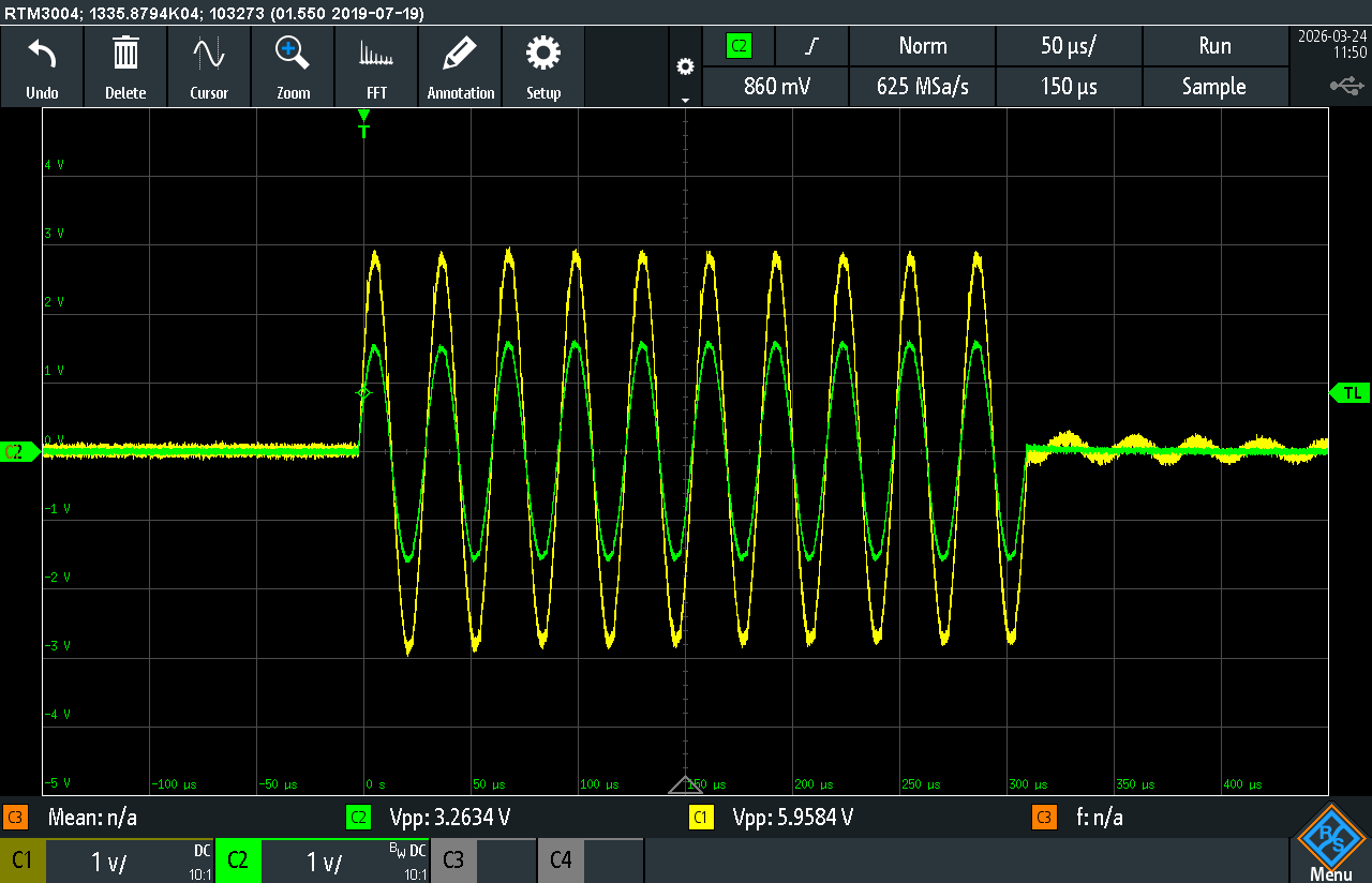
Amplification
After the AC coupling of the DAC output, the ADA4511-2 amplifies the signal by a factor of around 2 considering losses in the path. The corner frequency is at 3.710 kHz, which the DAC signal passes with very little attenuation at ~32 kHz.
A LTSpice simulation for the setup is found in pcb/simulation/SpeakerSimulation.asc.
Lab measurement