FSK Communication
Introduction
Telecommunications is undeniably fascinating, yet it has historically faced significant technical challenges. For decades, wireless communication has been dominated by radio‑frequency (RF) electromagnetic waves. While effective, RF can be limited in certain contexts, such as severe attenuation in saltwater or heavy interference in crowded spectrum. This leads to an interesting alternative: why not use ultrasound as a communication medium instead? By shifting from electromagnetic to acoustic propagation, we can develop systems that are well suited to short‑range, EMI‑resilient data exchange in specific environments, though acoustic links have their own constraints on range and bandwidth.
Since we are still dealing with waves, the same fundamental principles of signal modulation apply. In digital communication, three primary classes are commonly used to encode information onto a carrier:
- Amplitude Shift Keying (ASK): Varies the signal’s amplitude. Simple to implement but susceptible to ambient acoustic noise and amplitude fading.
- Frequency Shift Keying (FSK): Varies the carrier frequency among discrete tones. Often more resilient to amplitude fluctuations and certain noise/multipath conditions, at the cost of bandwidth.
- Phase Shift Keying (PSK): Varies the signal’s phase. Can be spectrally efficient but may be sensitive to phase distortion.
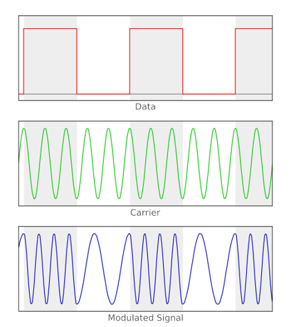
Our main focus will be on FSK, which is often robust for acoustic links under typical noisy conditions. Specifically, we will implement binary FSK (BFSK). This method uses two carrier frequencies: we assign the bit ‘0’ to a base frequency \(f_0\) and the bit ‘1’ to a higher frequency \(f_1\), separated by a defined spacing \(Δf\). As illustrated in the diagram, data is transmitted by switching the frequency of the acoustic wave between these two predefined values. By sending these controlled bit sequences, we can effectively encode and transmit data and text through ultrasonic waves.
Binary FSK (BFSK) signal generation
Goertzel Algorithm
To decode these frequency shifts, we need an efficient way to detect a small set of tones in a continuous stream of acoustic data. While the Fast Fourier Transform (FFT) is the standard tool for wideband spectral analysis, it is not the most efficient choice when only a few specific frequencies are of interest. In such cases, the Goertzel algorithm is more efficient, as it directly evaluates selected Discrete Fourier Transform (DFT) bins.
Our system uses the Goertzel algorithm to evaluate the two predetermined tones used by BFSK (\(f_0\) for bit ‘0’ and \(f_1\) for bit ‘1’). Goertzel computes the energy of a specific frequency component over a block of samples, enabling direct symbol detection.
Let \(F_s\) be the sampling rate and \(N\) the number of samples per symbol (bit) window. For a tone at frequency \(f\), define:
\[\omega = 2\pi \frac{f}{F_s}\]The Goertzel algorithm can be viewed as a two-stage digital filter. The first stage is a second-order IIR filter that processes the discrete-time input sequence \(x[n]\) to compute an intermediate state \(s[n]\):
\[\begin{equation} s[n] = x[n] + 2 \cos(\omega) \cdot s[n - 1] - s[n - 2] \label{eq:goertzel} \end{equation}\]where \(s[-1] = s[-2] = 0\) at the start of each symbol window. This structure is computationally efficient, requiring only one multiplication per sample per target frequency.
After processing the block, the second stage (effectively a FIR filter) computes the power of the frequency component:
\[\begin{equation} Power = s[n]^2 + s[n - 1]^2 - 2\cos(\omega) \cdot s[n] \cdot s[n - 1] \label{eq:power} \end{equation}\]The system compares the power values for \(f_0\) and \(f_1\) and decodes the bit based on which tone has higher energy.
Hardware Setup
To perform this modulated communication, the essential required components are a transmitter and a receiver. For this project, we use two SensEdu boards based on the Arduino GIGA R1 WIFI:
- Transmitter (Tx): Uses an ultrasonic transducer to generate and emit the modulated acoustic waves.
- Receiver (Rx): Captures the incoming signal using the onboard MEMS microphones.
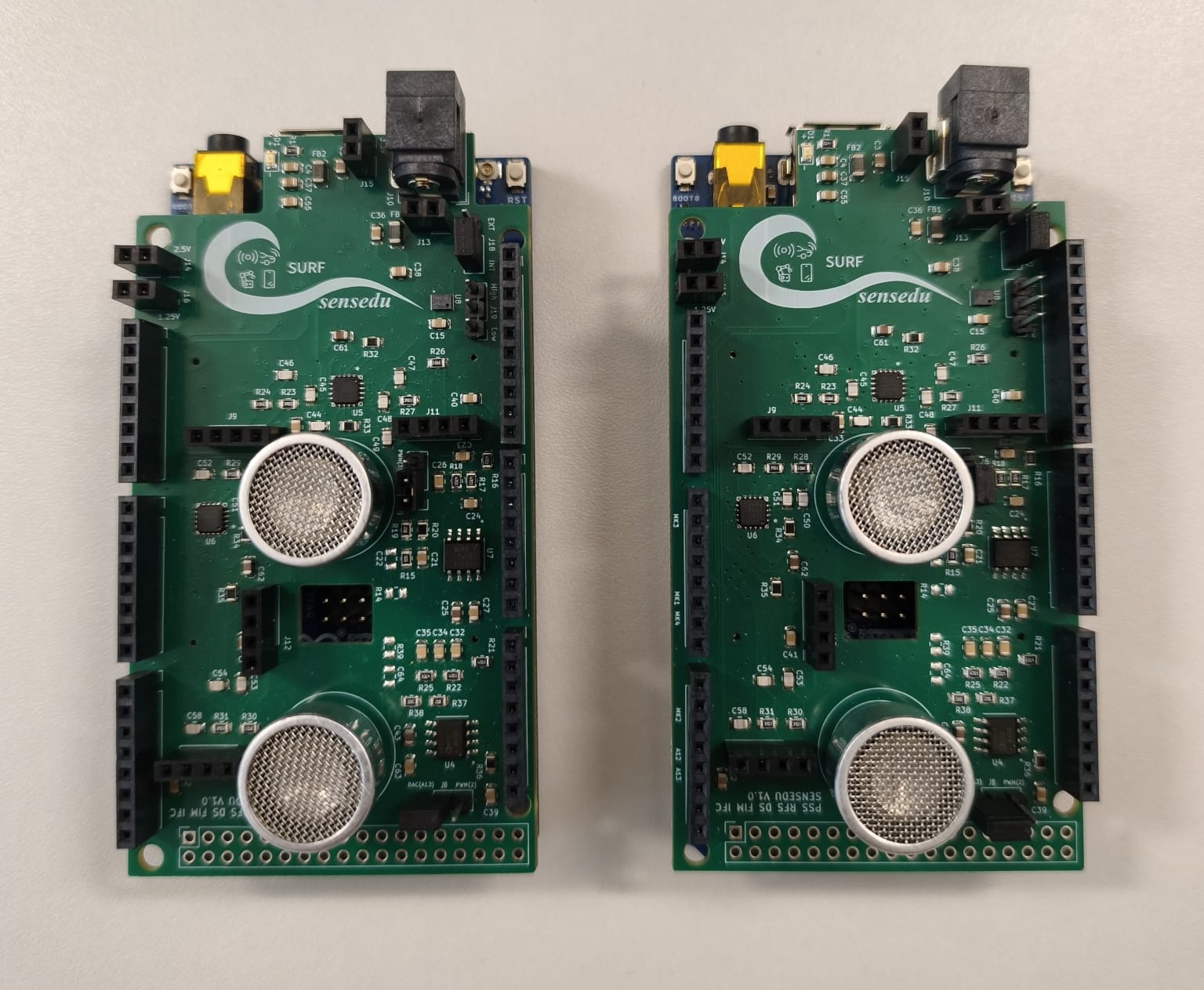
The two boards are placed directly in front of each other to ensure a direct transmission path and to minimize signal attenuation caused by the environment. For our tests, they were separated by a distance of 40 to 100 cm, providing a stable channel for data exchange.
The communication between the two boards is completely wireless, each board needs only USB / USB-C connection to the computer.
Software Implementation
The software architecture is divided into two main modules: the Signal Generation on the transmitter side and the Digital Signal Processing (DSP) on the receiver side.
Transmitter
The transmitter’s primary role is to convert digital data into a continuous FSK-modulated acoustic wave, i.e. the current implementation handles waveform synthesis directly, ensuring a more flexible and integrated approach. In order to do that, the system utilizes the internal 12-bit DAC to produce high-resolution sine waves. By switching between two target frequencies, the transmitter creates the necessary frequency shifts to encode information. To improve stability and frequency precision, a phase accumulation logic is defined for each frequency.
Due to the finite size of the hardware memory buffer, the maximum message length is set to 30 characters. This limit is calculated considering the 200 samples allocated per bit; this duration provides the ultrasonic transducer with sufficient time to stabilize and adapt to each frequency shift, ensuring a clean transition between logic states. With a 480 kHz sampling rate and 200 samples per bit, the frequency resolution is 2.4 kHz. We therefore select tones that land exactly on Goertzel bin centers, 31.2 kHz (13 × 2.4 kHz) and 36.0 kHz (15 × 2.4 kHz), while keeping them near the transducer’s ≈33 kHz resonance to maximize acoustic efficiency and detection robustness.
The system uses SENSEDU_DAC_MODE_BURST_WAVE to transmit tone bursts. By connecting the dma_buffer directly to the DAC through DMA, the transmission stays stable and avoids any gaps or delays between the bits. For more information about DAC configurations, go to DAC_Burst_Sine.
// Maximum number of characters to send between separate messages
const uint16_t MAX_MESSAGE_LENGTH = 30;

// ASCII standard 1 byte per letter
const uint16_t BIT_PER_CHARACTER = 8;

// Arbitrary chosen number to send ~10-12 cycles per bit
const uint16_t SAMPLES_PER_BIT = 200;
const uint16_t SAMPLES_PER_CHARACTER = SAMPLES_PER_BIT * BIT_PER_CHARACTER;

// x4 extra characters reserved for the preamble
const uint16_t PREAMBLE_LENGTH = 4;

// Endline character for finishing the message
const uint16_t ENDLINE_LENGTH = 2;

// DMA buffer size
const uint16_t MAX_LUT_SIZE =
        (MAX_MESSAGE_LENGTH + PREAMBLE_LENGTH + ENDLINE_LENGTH) * SAMPLES_PER_CHARACTER;

volatile SENSEDU_DAC_BUFFER(dma_buffer, MAX_LUT_SIZE);
SensEdu_DAC_Settings dac_settings = {
    .dac_channel = DAC_CH1,
    .sampling_freq = SAMPLE_RATE,
    .mem_address = (uint16_t*)dma_buffer,
    .mem_size = MAX_LUT_SIZE,
    .wave_mode = SENSEDU_DAC_MODE_BURST_WAVE,
    .burst_num = 1
};
The main core of the transmitter is the construct bit function, which translates logical bits into physical sound waves. During the process, the function calculates a sine value for every sample and constantly updates the phase to ensure the wave is smooth, avoiding any sudden jumps between bits. Finally, the signal is shifted and scaled to use the full range of the hardware.
// Fills the buffer with one bit worth of data
void construct_bit(bool bit, float* phase, uint16_t* buf_pos) {
    float phase_inc = bit ? PHASE_INC1 : PHASE_INC0;
    for (size_t i = 0; i < SAMPLES_PER_BIT; i++) {
        *phase += phase_inc;
        if (*phase > TWO_PI) {
            *phase -= TWO_PI;
        }

        float sample = sinf(*phase);
        dma_buffer[*buf_pos] = (uint16_t)((sample + 1.0f) * 2047.5f);
        (*buf_pos)++;
    }
}
We use an oscilloscope to verify how the signal is transmitted. The trace below shows an example captured while sending a single character.
![]()
Once we have the logic to create a single bit, we need to organize the entire message in memory. The construct_buffer function acts as the “architect” of the transmission by preparing a continuous stream of data. First, the system clears the memory buffer to ensure no old data interferes with the new message. Then, it generates a Preamble, which is a repetitive pattern of ‘1’s and ‘0’s. This is crucial because it acts as a “wake-up call” for the receiver, allowing it to detect that a transmission is starting and to synchronize its clock. Next, the function breaks down each character of the message into its 8 individual bits and calls the construct_bit function to fill the buffer with the corresponding 31.2 kHz or 36 kHz waves. It also includes an ending line, so that the receiver knows when to stop recording.
// Fills the buffer with the message encoded via 12-bit values of ASCII characters
void construct_buffer(uint8_t* data, uint8_t num_bytes) {

    // Position in a LUT buffer
    uint16_t position = 0;

    // Current phase of the output sine wave
    float phase = 0.0f;

    // Clear the entire LUT first with DC level
    for (size_t i = 0; i < MAX_LUT_SIZE; i++) {
        dma_buffer[i] = 0x000;
    }

    // Preamble 0xFF00FF00
    for (size_t i = 0; i < PREAMBLE_LENGTH; i++) {
        for (size_t j = 0; j < BIT_PER_CHARACTER; j++) {
            construct_bit((i + 1) % 2, &phase, &position);
        }
    }

    // Payload
    for (size_t byte_idx = 0; byte_idx < num_bytes; byte_idx++) {
        uint8_t cur_byte = data[byte_idx];
        for (size_t bit_idx = 0; bit_idx < 8; bit_idx++) {
            bool bit = (cur_byte >> (7 - bit_idx)) & 1;
            construct_bit(bit, &phase, &position);
        }
    }

    // Endline
    for (size_t i = 0; i < ENDLINE_LENGTH; i++) {
        for (size_t j = 0; j < BIT_PER_CHARACTER; j++) {
            construct_bit(0, &phase, &position);
        }
    }
}
Finally, send_message function is responsible for the actual execution of the transmission. It first triggers the buffer assembly to prepare the entire message in memory. Once the data is ready, it enables the DAC hardware to begin streaming the acoustic wave.
// Transmits the entire constructed message
void send_message(uint8_t* data, uint8_t num_bytes) {
    construct_buffer(data, num_bytes);
    SensEdu_DAC_Enable(DAC_CH1);
    while (!SensEdu_DAC_GetBurstCompleteFlag(DAC_CH1));
    SensEdu_DAC_ClearBurstCompleteFlag(DAC_CH1);
    SensEdu_DAC_Disable(DAC_CH1); // Clean shutdown
}
The final component of the transmitter is the main loop, which acts as the “control center” of the system. Its primary task is to constantly monitor the Serial Port for any incoming text from the user. Once the message is typed, the loop ensures it does not exceed the MAX_MESSAGE_LENGTH, and also performs a quick clean up by removing any extra line breaks. Finally, the system prints and sends the message through an acoustic wave into the air.
void loop () {
    if (Serial.available() > 0) {
        length = 0;
        while (Serial.available() > 0 && length < MAX_MESSAGE_LENGTH) {
            message[length] = Serial.read();
            length++;
        }

        while (length > 0 && (message[length - 1] == '\n' || message[length - 1] == '\r')) {
            length--;
        }

        if (length > 0) {
            Serial.println("Transmitted message: ");
            Serial.write(message, length);
            Serial.println("");
            send_message(message, length);
        }
    }
}
Receiver
Once the ultrasonic wave reaches the receiver, we acquire and process the signal. We include the library and set the main parameters, choosing the sampling rate at 240 kHz, an integer submultiple of the transmitter’s 480 kHz rate. Using a lower sampling rate (with our fixed analysis window) increases frequency resolution and reduces data throughput while still comfortably capturing the 31.2/36 kHz tones. We record each iteration during 3 seconds, that can be change but always matching MATLAB configuration.
// Recording time per one message
static const uint16_t MSG_RECORD_WINDOW_SEC = 3;

// Must be multiple of TX SR
static const uint32_t SAMPLING_RATE = 240000;
The ADC runs continuously and writes into a double (ping‑pong) buffer, so one half can be forwarded while the other is filling, avoiding gaps. Each chunk is then sent to MATLAB for decoding, and basic error checks report and stop the system if something unexpected occurs. To get more information about circular DMA mode go to ADC_1CH_DMA_CIRCULAR.
static ADC_TypeDef* adc = ADC1;
static const uint8_t ADC_PIN_COUNT = 1;
static uint8_t adc_pins[ADC_PIN_COUNT] = {A1};

SensEdu_ADC_Settings adc_settings = {
    .adc = adc,
    .pins = adc_pins,
    .pin_num = ADC_PIN_COUNT,

    .sr_mode = SENSEDU_ADC_SR_MODE_FIXED,
    .sampling_rate_hz = SAMPLING_RATE,

    .adc_mode = SENSEDU_ADC_MODE_DMA_CIRCULAR,
    .mem_address = (uint16_t*)dma_buffer,
    .mem_size = DMA_BUFFER_SIZE
};
Signal Decoding in MATLAB
Now that the full message has been sent to MATLAB, we can start decoding. First, set the receiver parameters: sampling rate, samples per bit (N), the two FSK tone frequencies, the preamble, etc. Make sure every value matches the transmitter and capture firmware.
Be careful setting the parameters, everything must match with both receiver and transmitter.
Our main entry point is decode_fsk_message. At its core, run_goertzel splits the recording into bit‑sized pieces, checks a few nearby start positions for each piece, compares which of the two target tones is louder, and outputs the difference. Positive values mean the higher‑frequency tone wins; negative values mean the lower‑frequency tone wins.
% Goertzel Coefficient (must be integers)
k = (f/fs) * samples_per_bit + 1;

% (Affects a lot the accuracy vs performance trade-off)
HOP_STEPS = 5;
HOP = N/HOP_STEPS;

function [energy_diff, x_labels] = run_goertzel(data, hop, N, k)
    bit_num = floor((length(data) - N)/N);
    hop_num = N/hop;

    energy_diff = zeros(hop_num, bit_num);
    x_labels = zeros(hop_num, bit_num);

    for j = 1:hop_num
        for i = 1:bit_num
            idx = (j-1)*hop + (i-1)*N + 1;
            segment = data(idx : (idx + N - 1));

            dtft1 = abs(goertzel(segment, k(1)))^2;
            dtft2 = abs(goertzel(segment, k(2)))^2;

            energy_diff(j, i) = dtft2 - dtft1;

            x_labels(j, i) = idx + N/2;
        end
    end
end
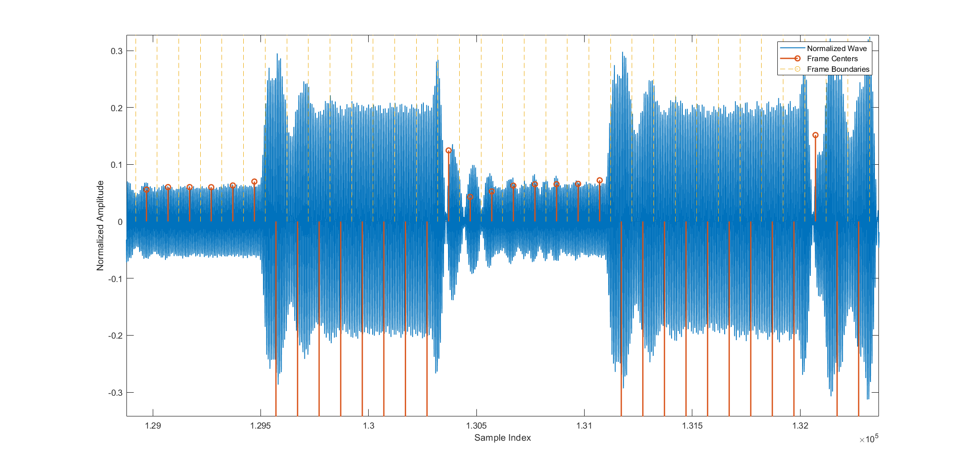
The figure below shows the MATLAB visualization of the captured data. The waveform is segmented into equal, bit‑sized chunks (yellow). Each chunk contains a tone burst at either the lower or the higher FSK frequency, forming the transmitted bit pattern. Although some amplitude noise is present, the frequency shifts are clear and the transitions between chunks are smooth. The differing amplitudes of the two tones also highlight the method’s robustness: even though the tones are offset from the transducer’s resonance and thus attenuated differently, the decoder still separates them reliably.
Next step will be to detect the preamble of our signal. In order to do so, we have implemented the function analyze_preamble, that scans our measured energy difference, slides the preamble pattern across it, and finds where it fits best. Finally, it chooses the alignment (hop) with the best overall score and returns the one that fits best, the position where the preamble start, and the result of the strongest match.
% Preamble 0xFF00FF00
PREAMBLE = [1 1 1 1 1 1 1 1 0 0 0 0 0 0 0 0 1 1 1 1 1 1 1 1 0 0 0 0 0 0 0 0];

function [best_hop, best_preamble_pos, best_conv] = analyze_preamble(energy_diff, preamble)
    hop_num = size(energy_diff, 1);
    correlations = zeros(1, hop_num);
    preamble_pos = zeros(1, hop_num);

    for i = 1:length(correlations)
        data = energy_diff(i, :);
        c = abs(conv(data, fliplr((preamble * 2) - 1)));
        [correlations(i), idx] = max(c);
        preamble_pos(i) = idx - length(preamble) + 1;
    end

    [best_conv, best_hop] = max(correlations);
    best_preamble_pos = preamble_pos(best_hop);
end
Last but not least we perform the decoding of the message into ASCII and plot both the result of the convolution and Goertzel. We can finally see our transmitted message on the command window.
Showcase
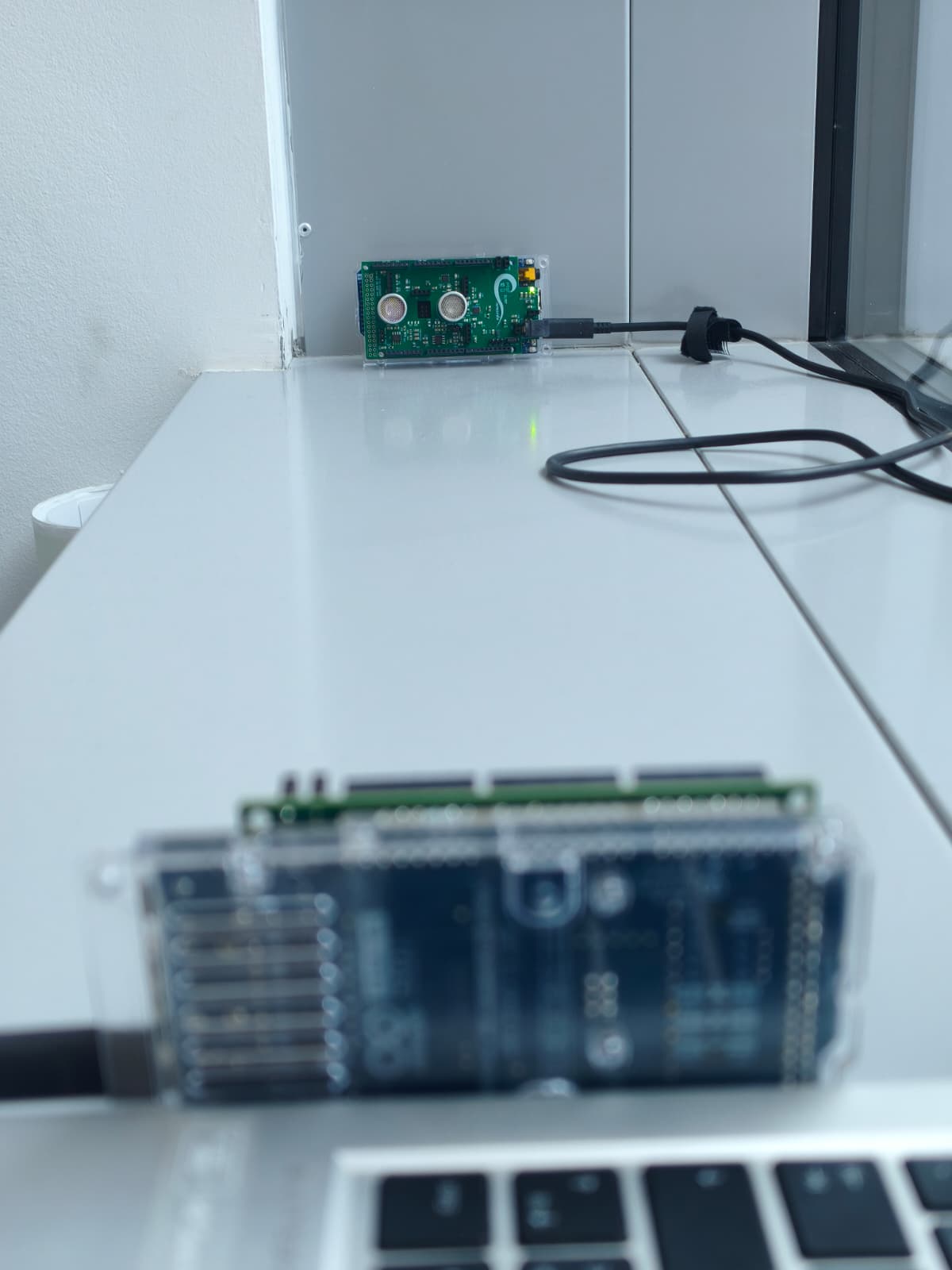
This last section shows a real test using the FSK communication. While placing the boards in front of each other at a distance close to one meter, we upload both receiver and transmitter codes to the respective Arduino board, and run the MATLAB code.
You will probably need to change the ARDUINO_PORT as well as the ARDUINO_BAUDRATE to match the receiver.
Once you run the code in the transmitter you can open the serial monitor and start typing your message.
![]()
You will see the result in the MATLAB Command Window.
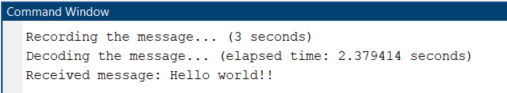
The only thing left to do is to enjoy!